Fixing Nikon D80 “Err” Aperture Control / Shutter Problem … by David HK September 2018
Fixing Nikon D80 "Err" Aperture
Control / Shutter Problem … by David HK September 2018
Symptom:
My rarely used 11 years old Nikon D80 DSLR (with less than 18000
shutter counts) suddenly displayed “Err” message after not being used for
around 9 months. The symptom was when you pressed the shutter, either “Err”
flashing on the top LCD, or you can hear the shutter is moving “lazily” and no
mirror lock up sound (ie not a complete shot), view finder went black, no photo
saved, or sometimes, if you are lucky, it can take the first photo after you first
switched on the camera.
Cause:
After googling around, it is caused by the fault of a small plastic
wheel that determines the position of the Aperture Control (and the mirror). On top of the wheel, there is a piece of
metal with 2+4 legs pointing upward, when the Aperture Control motor is
spinning, which connects to this wheel, the position of these legs will
determine the position of the Aperture Control and the mirror. However, this piece of metal is held on to
the wheel via two plastic rivets, and one of the rivet caps has come off,
making the legs move slightly out of place when the wheel is spinning.

The Fix:
The fix is to disassemble the camera to get access to this wheel, then
fix the loose rivet cap. Again, I googled
around, generally there are 2 solutions, A) find a tiny screw (in fact 2, while
you are doing it, may as well replace the other plastic rivet with a metal
screw), which is around 0.5-0.7mm diameter x 2-3mm long, and need to drill a
small hole before screwing to prevent breaking the plastic wheel, as shown here
by someone in the internet (not mine).

Or B) use super-glue to cover the 2 plastic rivets, as shown here by
someone from Taiwan (not mine),

I glue the whole metal piece, and glue back the broken rivet cap back,
hoping this will provide additional force to secure the metal piece. And here is my wheel after applying some
super-glue:

Resources:
I learned how to disassemble and reassemble the D80 from these 2
youtube videos, so thankyou both:
Also I downloaded the D80 repair manual from this site,
the manual shows you how to disassemble and reassemble the whole
camera. But most of the parts are no
need to disassemble to fix this wheel, which I will show you in this blog. Note that some of the detailed pictures are from this manual.
Tools:
-
The Philips #000 size screwdriver, the one that
used for repair iphone
-
Soldering iron (as you need to disconnect at
least 1 wire, preferably a few more)
-
Writeable white paper sticky tape (the one that
can peel off easily), use this to label the different screws number, and to secure
some disassembled parts that are hanging around by 1 or few wires, otherwise
the wires will be broken easily.
-
A multi-partition box to separate all the
different screws used by the camera, and write a label of the screw# inside,
there are more than 15 different screws used!
-
A magnifying glass to help to see while
disassembling and soldering.
-
A plastic prying tool
-
Your fingernail, to pry out some of the micro
PCB connectors.
-
Cutter knife, to open the pop-up flash
-
2K ohm resistor or 5W light bulb to discharge
the flash capacitor
-
A piece of card or paper without any dust to
cover the sensor while the camera front body is out, around 35mm x 22mm (larger
than the sensor)
-
A small piece of thick cloth (eg a kitchen cloth
folded 2 times) of about 25 x 25 cm for the camera to rest on, as we will be
shifting the camera body in different angles during the process, this is to
protect the exposed components and circuit by moving the cloth instead of the
bodies.
Here are most of the tools I used:

Steps:
To access the Aperture Control plastic wheel, we need to separate the
camera front and rear bodies, the front body is from the lens mount ring to the
shutter, the rear body is what’s left behind.
You can see the actual photo sensor sitting at the back of the rear body!
- Download the D80 repair manual (the page# I provided are the pdf file page#, not the document page#)
- Place a small piece of thick cloth on the table, then the camera.
- Takeout the 2 (#692) +1 (#658) +4 (#657) screws at the bottom of the camera (page 6), note that other 2 larger screws are no need to takeout.

4. Remember to label
the screw# into separate partition box, you must do this for every different
screw#, otherwise you will regret it, like I did! ☹
5. Then take out the 2 (#657) + 2 (#656) screws from the sides of the back cover (page 6).

6. Before you separate
out the back cover, need to discount the LCD PCB connection, as shown in page
7 of the repair manual.

7. There are 2 screws #691
inside the pop-up flash, you can use the back of a cutter knife and insert into
the LHS gap at the back of the flash then slide towards the front, there is a trigger
near the middle which will pop open the flash. (page7)
8. Skip page 8, now on page 9, takeout the 2 screws #691 at the top of the lens mount centre cover, and the AF/M switch (#121) at the side (there is a screw (#659) underneath the dot cover (#124), which is just a piece of sticky plastic paper, can use the edge of a cutter or the tip of a sharp tweezers to remove it), then the centre cover can be removed (you can put back the lens mount cover afterward to protect the mirror)
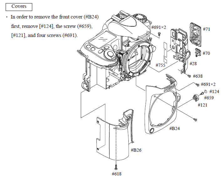
9. Takeout the 1 screw
#618 inside the battery compartment (RHS), then the battery compartment can be
removed. (page 9)
10. Takeout the 1 screw
#638 at the bottom of the LHS cover, then the whole LHS cover can be removed.
(page 9)
11. Now you can see
there is a very large capacitor on the LHS, this is the flash current storage,
even if you disconnected the battery for a long time, there may still be high
power current inside. Need to discharge
it via a 2K ohm resistor as shown. If
you don’t have a resistor, a small 5W light bulb may do the job. (page 9)

12. There are 4 screws (#634)
at the back of the camera that hold on to the front body. 2 in the middle behind the large PCB at the
back, and 2 at the top behind the eyepiece.
To takeout the 2 in the middle, need to remove the metal sheet and open
up the large PCB at the back.
13. Takeout the 6 screws
(#683) at the back, then remove the metal sheet. (page 10)

14. To open-up the
large PCB, need to takeout the 1 screw (#683) at the top, 2 PCB connectors, and
1 white harness on the side. No need to
remove the large white harness and large PCB connector at the bottom (need to
retain these to protect the 2 grey wires solder joints), as all I need is to
open up this large PCB in order to access 2 screws. (page 10)

15. Now takeout the following
screws from the top cover (not the top cover yet as
there is a PCB connection attached to it): remove the 1 (#656) + 1
(#629) side screws, and 2 (#686) back screws, plus the adjustable diopter roller
(#288), the cover of which is just a piece of sticky
plastic paper, can use the edge of a cutter or the tip of a sharp tweezers to
remove it, then you can see a screw (#288).
Also there is a small screw (#624) underneath the right hand corner of
the top cover need to remove. (page 12)

16. There is a PCB
connection attached to the top cover, so open up the top cover slowly from the
RHS (as on the LHS, there are a bunch of wires
connected which we are not going to remove), on the RHS you will see a
PCB connector, use a plastic pry or your fingernail to tilt up the connector
and remove the connection: (page 12)

17. So once the top
cover is removed but with a bunch of wires still connected on the LHS, I used a
paper sticky tape to tie the top cover and the camera strap ring on the LHS, so
the force is rest on the sticky tape instead of the connection wires. This is because during the remaining process,
both the camera and the top cover are moving around, we don’t want any
connected wire solder joints to break.
18. Now remove the
eyepiece mold 2 screws (#291) (page 21)
19. Then the 4 screws
(#634) at the back that hold on to the front body can be accessed and removed;
2 underneath the eyepiece and 2 underneath the big PCB at the back. (page 21)

20. Go back to the top
RHS, we need to remove the sub-PCB in order to remove 2 PCB connectors beneath
it before we can remove the front body.
To do that, first remove 3 PCB connectors that are attached to the
sub-PCB, then takeout 2 (#640) + 1
(#623) screws, no need to unsolder the 2 AF-assist black wires nor the grey
wire. (page 20)

21. The Sub-PCB is connected
to the underneath main PCB via a multi-pins rectangle connector (as circled in
yellow below), use a plastic pry’er to slowly jack up and separate the sub-PCB
from the main PCB beneath it. (page 20)

22. Now this sub-PCB is
loosely connected to the rear body by the little grey wire, to avoid possible
damage to the wire solder joint, I taped the sub-PCB to the camera strap ring.
23. Now on the Main PCB
above, need to disconnect the 2 PCB connectors as circled in white above. No
need to takeout the Main PCB. (page 20)
24. During my 3rd
attempt to disassemble and assemble the camera, the wire joints of the black
& red Front body FPC got disconnected because of too tight and short wires. So I would suggest to unsolder these 2 black
& red wires to give yourself more room and buffer to more things around
during the remaining steps. (the blue
and orange wire joints can stay) (page 20)
25. Now at the front of
the camera, there are 5 screws need to takeout; 2 (#699) + 1 (#621) + 2 (#615)

26. Lastly, at the
bottom of the camera, there is a black grounded wire solder joint (as circled
in yellow), this must be unsolder before the front body can be separated out
from the rear body:

27. Now the front body
can be carefully taken out by pulling the lens mount ring, be careful, there
are still some wires attached, but we should have enough room to access the Aperture
Control wheel.
28. Once the front body
is out (see below), place it upside-down with the lens mount ring resting on
the table, and the shutter facing the ceiling.
We will be taking off the Aperture control unit as circled in yellow,
the plastic wheel is inside the bottom end as circled in red. (just a side
note regarding the D600 & D610 oil/dust spots appearing in the top left corner
of photos, which means the bottom right corner of the sensor, as this is where
the motor gear and the mirror swing arm mechanism is, and if there are too much
grease oils or generated friction dust in these mechanism, with a larger full frame sensor, it could be the root
cause of oil spots appearing in the top left corner of photos in these camera! Just my thought.)

29. Now look at the
rear body, with the large back PCB resting on the table, and the sensor is
facing the ceiling, a beautiful sensor, but any dirt can easily drop on to the
surface, so you need to cover the sensor with a piece of plastic or paper card cut
into suitable size to protect it while you are working on the camera.

30. As mentioned in the
beginning, should place a piece of square thick cloth on the table for both
bodies to rest on, so the delicate circuit and exposed parts are not being
scratched when we move the bodies in different angles by moving the cloth, not
the actual bodies.
31. To access the problem
wheel, we need to takeout the Aperture Control unit (with the motor), there are
4 screens need to takeout, as circled in yellow. The 5th screw highlighted in red I
am not 100% sure whether need to take out or not, my current memory said no.


32. Be careful with the
little tension spring #214 at the LHS below the top small screw, here I shown
mine below, it has at one point disconnected without me noticing (see above
picture), try not to, because it is a pain to get it back on. To get it back on, need to first connect the
inside peg first (circled in green), with the spring position in a “V” angle,
ie the centre hole is pointing downward when the Aperture Control unit is screwed
back on. If you look in closely (eg via
a magnifying glass), you can see both pegs have a small tooth extended towards
inside, you need to go through the tooth first in order to put the spring hole
onto the pegs. Also need to connect the
tension spring on both pegs first before tightening back any of the screws.


33. Once the 4 screws
are taken out, pry slowly to get the flat black plastic plate out, beneath it
is the wheel that we want to take out.
Once the top plate is out of the way, remember to take a photo of the
wheel original orientation, because there are 2 different orientations to put
it back, and if you get it wrong, the mirror will swing incorrectly and never
back to the rest position after shutter is pressed.
34. I captured the original
wheel position from a YouTube video (I forgot to take a photo of mine before
taking my wheel out!) (not mine):

35. You can see the
back of the wheel is not 360o symmetrical.

36. The rest of the Aperture
Control components including the motor will come off as well (but with 4 wires
still attached, 2 if the red & black wires have been unsoldered earlier).
37. Pay attention
beneath the wheel, there is 1 metal ring attached to the centre shaft, and 2
plastic rings attached to 2 side shafts beneath the wheel, these rings are
oily, and don’t lose them!
38. After taken out the
wheel, I found exactly what is the problem, that one of the rivet cap has come
off.

39. I used the
super-glue method to secure the piece of metal on the wheel. I leave the
super-glue to dry overnight, yes it is overkill for such long time, but it was
midnight, too tried for me to continue, and I want to do a careful inspection
on the outcome of the super-glue, just to double check if it is strong enough
to hold on to the metal piece. Also, if
the super-glue is not 100% dry, you may have permanently fixed the wheel
against the mechanism!

40. Here is a shot of
what’s behind the top plastic plate.
When the wheel is spinning by the aperture / shutter motor, it will know
the position of the aperture / shutter.

41. Above you notice
the tension spring #214 was still intact in my first attempt!
42. Before you put the
front body back, open the lens mount cap to double check the mirror is in the
“rest” position. If not, you can turn
the problem wheel (without the top plastic plate in place yet) downward
direction (clockwise) until the mirror is in the “rest” position.
43. Now put it back
carefully in the reverse order. (easy to say … 😊)
44. You may find you’ve
dropped 1 or 2 pieces of the small copper “finger” and don’t know where it
belongs, they are just inserted behind the lens mount at the top on both sides.

45. Here is the
reassembled D80, hooray!

46. This photo was
taken after the fix:

47. At 100% crop:

48. At 200% crop:

49. At 300% crop

50. I hope I have given
enough info for anyone who wants to try to repair their old D80 Err Aperture /
Shutter problem, happy fixing!
- E N D -
Appendix:
don't be scare of these photos :)


don't be scare of these photos :)


Bravo, ottimo lavoro! Adesso devo farlo anche io.
ReplyDeleteThank you so much for this step by step tutorial. I am very grateful. I fix my camera!!!
ReplyDeleteI just used this blog to fix my D80! My old camera works again! Thank you so much for the clear tutorial. My only confusion was Step 31. You DO need to take the red circled screw out. Also, if you could include labels for each screw (like you do in your other steps), that would be helpful. Thanks again!
ReplyDeleteThank you so much!!! Worked like a charm - I'm an engineer and tinker a lot but some of the connectors could be tricky for people doing this for the first time. Best instructions ever. Professor David!
ReplyDeleteThanks for the instructions, I was able to fix my camera. Unfortunately I didn’t glue the metal piece properly, I had to redo the whole fix a couple of times until I found the error. So be aware and apply enough glue on the metal contact and plastic wheel. When not completely glued down, the middle part of the metal piece got pushed up by the brushes and caused a short, so be aware. Also I did bent a small pin in one of the white harnesses at the mainboard at the back when reassembling (screen and sd not working) - was able to fix that in the end and now everything is fine.
ReplyDeleteBy mirror in rest position you mean the mirror down? I checked it, the grey wheel is in your same position as showed in step 34 but when I turn on the camera and press the shutter button, the mirror swing multiple times and never come back down, do you have suggestion?
ReplyDeleteVill du byt iphone batteri eller reparera iPhone glas skärm glas och display på ett billigt säkert och effektivt sätt i Göteborg Borås Stockholm Umeå Halmstad eller Örebro får du kvalificerad hjälp med fokus på noggrannhet och långsiktiga lösningar.
ReplyDelete