Flashing Tiny Frsky 8CH Receiver from Banggood… by David HK October 2016
Flashing Tiny Frsky 8CH Receiver from Banggood… by David HK October
2016
After my experience with flashing midelic DIY Frsky firmware to
AC801/F810 (see link below),
I feel more comfortable into doing it again, this time, to Banggood’s Tiny
Frsky 8CH Receiver Compatible, which is a clone, and not supported by midelic, so do it at your own risks.
I bought this Tiny RX for my new Lantian 105 micro brushed build
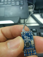
RX: Tiny Frsky 8CH Receiver
Steps:
1. Install the driver for the USBASP programmer (if this is the 1st
time you use your USBASP)
To use the USBASP, need to install the USB driver (I am
running win7), to do that, use zadig_2.2.exe (from below URL) which will
install the driver while connected the USBASP. In Options->List all devices,
then you should see the usbasp driver to install.
for more details visit this link:
http://www.fischl.de/usbasp/
**warning: must made sure the USBASP is 3.3V output, not 5V (there is
either a switch, or need to remove a resistor at the back of the USBASP,
otherwise will fry your RX.
2. Prepare the USBASP hardware and wiring:
The flashing pins in the RX is on the back right hand side, as in the
photo below
MISO
+3V (note that some diagrams in rcgroup listed it as +5V, should be +3V)
MOSI
SCK
RST
GND
While in the USBASP, the 10 pins layout is shown in the diagram below:
So the mapping is per below:
RX
|
usbasp pins
|
MISO
|
10
|
+3V
|
1
|
MOSI
|
2
|
SCK
|
8
|
RST
|
6
|
GND
|
3
|
I used 6 servo wires to connect to the corresponding pins in the usbasp
socket, sequentially so that the 6 wires can be lined up to match with the pins
in the RX. As the RX pins are very close
together, I don’t think I can manage the soldering at this close, and this is
supposed a one off flashing usage, so I decided to just hand hold the servo
wires while flashing. But the RX pins
are closer than the width of the servo plastic connectors that line up
together, so I need to take out the plastic connectors, then use tape to
insulate the connectors and bound the wires together in a straight line, the
width of the wire pins is just about the same as the RX pins. The whole
flashing duration only last for 10 to 20 seconds, so I think I can manage with 2
hands holding, and asked my wife to help to click the “write” button to start
the flash! J
3. Actual flashing
Get the latest RX firmware from below link, I downloaded FrskyRx_F801_TELEMETRY_PFS_SBUS_071016.hex
I used the AVR Burn-O-Mat GUI to do the actual flashing, download from
below link. It requires Java runtime.
Steps:
1.
Click Settings -> AVRDUDE,
a.
set the avrdude.exe & avrdude.conf location
(I’ve avrdude installed already when I installed the eepskye GUI for my Turnigy
XR9 Pro tx radio)
c.
Port set to your connected USB com port or just
usb
2.
In main screen,
a.
set AVR type = ATmega328p
b.
under Flash, select the FrskyRx hex file that
was downloaded from the RC group (ie in
my case, it is FrskyRx_F801_TELEMETRY_PFS_SBUS_071016.hex)
c.
under Flash, click the Write button - - this
will do the actual flashing of the firmware!
It takes around 10-20 seconds, you will see Reading …. Writing ….
Reading… where … are a few lines of notification of what it was doing, at the
end you will see “avrdude.exe done. Thank you”.
Note that with this RX, I only able to get RSSI telemetry but not the
voltage telemetry, I guess I will leave it at that and use my radio timer to
alert me when to land. Or the micro quad will lost power and fpv signal will
drop! J


It can also be flashed with an Arduino (running avrisp)
ReplyDeleteOpen windows command window
cd to avrdude
Backup original firmware:
avrdude -C avrdude.conf -c avrisp -P COM4 -b 19200 -p m328p -U flash:r:original_firmware.bin:r
Flash new firmware:
avrdude -C avrdude.conf -c avrisp -P COM4 -b 19200 -p m328p -U flash:w:c:\quadcopter\receiver\FD802\FrskyRx_F802_24012017.hex
Adjust COMport and file locations
Connections:
Arduino USBASP
5V ———– VCC
GND ——– GND
D13 ———— SCK
D12 ———- MISO
D11 ———- MOSI
D10 ——— RESET
Thanks, that's nice to know.
ReplyDeleteÜdv.! Köszi a leírást! Megcsináltam a leírás alapján,ami lefutott mint neked a fenti képen,azóta nem működik a vevő! újra csatlakoztattam és a "Device signature = 0x000000 " hibát kapok. Erre mi a gyógymód? Bármilyen ötlet jöhet!
ReplyDeleteHi, did you actually see the successful message "avrdude.exe done. Thank you" at the end of the flashing?
DeleteI am sorry I don't know why you get device signature error as I am also new to this hobby.
I think you can try to flash it again as it is just a ROM memory in the RX chip, flashing means putting the program into the ROM. so one can always flashing the program into the ROM again and again.
I know this post is a year old but I do believe the code you flashed to this receiver makes it use it's RX pin at the top corner of the board for FRSKY telemetry. If you hook up a extra uart TX from the flight controller to that pin and push telemetry out on that uart on the FC you'll at least get the FC's reading of battery voltage
ReplyDeleteThanks for this extra info, good to know, will try it next time I do some maintenance with this little quad.
Delete